INDUSTRIAL PRODUCT
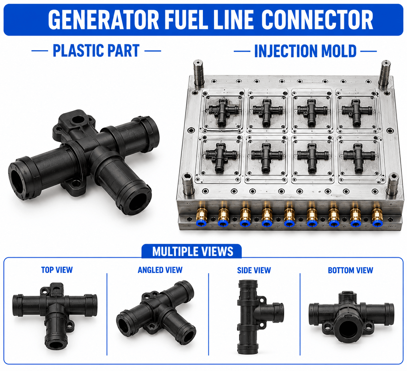
Generator Plastic Fuel Line Connector Mould and Moulding Service
₹20.00
Generator Plastic Fuel Line Connector Mould and Moulding Service | Renovator Appliances Ltd
Product Overview
Renovator Appliances Ltd manufactures precision plastic injection moulds and moulded components for the Generator Plastic Fuel Line Connector used to connect fuel lines with the fuel tank, carburetor, fuel pump, filter, or other fuel-system components in generator assemblies. The connector is designed to provide a secure fuel passage while maintaining accurate hose engagement and reliable connection geometry.
The mould is developed according to the required fuel hose inner diameter, connector outer diameter, internal flow passage, connection length, port configuration, sealing arrangement, mounting requirements, and available installation space. Depending on the generator design, the connector can incorporate straight, angled, stepped, barbed, threaded, or multi-port configurations.
Because the component is exposed to fuel and may experience vibration and temperature changes during generator operation, material selection and dimensional control are important for maintaining connection integrity and service performance.
The injection moulding process provides repeatable dimensions, accurate flow passages, consistent hose-retention features, and reliable production for OEM, ODM, prototype, and volume manufacturing requirements.
Key Features
Precision injection moulding for Generator Plastic Fuel Line Connector
Customized connector geometry according to fuel-system requirements
Accurate internal fuel passage
Controlled hose connection diameter
Barbed or stepped hose-retention profile
Straight, angled, or multi-port configurations
Secure fuel-line engagement
Controlled wall thickness
Accurate connection alignment
Smooth internal passage for unobstructed fuel flow
Optional threaded or mounting features
Designed for vibration-resistant installation
Suitable for fuel-system applications with appropriate material selection
Consistent dimensions for repeated assembly
OEM and ODM customization
Suitable for prototype and mass production
Industrial Applications
| Application | Use |
|---|---|
| Portable Generator | Connects fuel hoses within the compact fuel system |
| Petrol Generator | Provides connection between fuel-system components |
| Diesel Generator | Can be developed for suitable fuel-line applications according to material requirements |
| Generator Fuel Tank | Connects the tank outlet with the fuel line |
| Generator Carburetor System | Provides fuel-line connection to the carburetor |
| Generator Fuel Filter Assembly | Connects fuel hoses to filtration components |
| OEM Generator Equipment | Custom connector manufacturing according to equipment specifications |
Manufacturing Process
1. Product Design & Development
The connector is designed according to the fuel hose dimensions, required flow passage, connection type, fuel-system layout, operating temperature, vibration conditions, and installation space. CAD modelling defines the connector profile, internal passage, barbs, steps, threads, mounting features, and wall thickness.
2. Plastic Mould Design
The injection mould is designed to accurately form the connector's internal fuel passage and external hose-retention geometry. Core arrangements, parting lines, gates, runners, vents, cooling channels, and ejection systems are optimized for dimensional consistency and reliable mould filling.
3. Mould Manufacturing
The mould is precision-machined using suitable mould steel such as P20, H13, or S136 Steel based on production volume, material characteristics, dimensional requirements, surface finish, and expected mould life. Critical core and cavity features are inspected to maintain connection accuracy.
4. Injection Moulding
The selected plastic material is melted and injected into the mould cavity under controlled temperature and pressure. Cooling and cycle parameters are controlled to minimize dimensional variation and maintain the required internal passage, wall thickness, and hose-retention profile.
5. Finishing & Assembly Preparation
After moulding, connectors are trimmed and inspected for flash, gate marks, incomplete filling, and obstruction within the fuel passage. Components are prepared for assembly with the specified fuel hoses and mating fuel-system components.
6. Quality Inspection
Finished connectors are checked for overall dimensions, internal passage diameter, hose engagement dimensions, barb or thread geometry, wall thickness, alignment, surface quality, warpage, and fitment with the specified fuel-system components.
Raw Materials
| Material | Typical Application |
|---|---|
| Nylon / PA | Suitable for fuel-system connectors requiring mechanical strength and dimensional stability |
| POM | Suitable for precision connector geometries requiring dimensional stability and low friction |
| PP | Can be considered for compatible fuel-system applications after fuel and temperature compatibility validation |
| HDPE | Can be considered for suitable fuel-contact applications based on chemical compatibility |
| Engineering-Grade Plastic | Selected for demanding mechanical, thermal, and dimensional requirements |
| Fuel-Compatible Engineering Polymer | Selected according to the specific fuel type, temperature, pressure, and service conditions |
Material selection for a fuel-line connector should be validated against the actual fuel type, operating temperature, pressure, exposure duration, mechanical loads, and applicable customer or industry requirements. Not every conventional injection-moulding plastic is suitable for direct fuel contact.
Quality Control
Renovator Appliances Ltd checks the Generator Plastic Fuel Line Connector for:
Overall connector dimensions
Internal fuel passage diameter
Hose connection diameter
Hose insertion depth
Barb or stepped-profile dimensions
Thread dimensions where applicable
Port alignment
Wall thickness consistency
Flow-passage continuity
Flash inside the fuel passage
Sink marks and short shots
Warpage and dimensional distortion
Surface finish
Hose retention and fitment
Connection alignment
Mating-component compatibility
Fuel-contact material conformity
Batch-to-batch dimensional consistency
Where required by the customer's specification, additional fitment, pressure, leakage, or fuel-compatibility validation can be incorporated into the inspection and validation process.
Buyer Guide
When ordering a Generator Plastic Fuel Line Connector Mould and Moulding Service, buyers should provide the fuel hose inner and outer diameter, fuel type, required flow rate, connector dimensions, number of ports, connection style, insertion depth, barb or thread specifications, operating temperature, pressure conditions, vibration requirements, mounting arrangement, material requirements, colour, and production quantity.
A CAD drawing, 3D model, existing connector, fuel hose sample, or complete fuel-system assembly can be used for mould development. The connector and mating hose should be designed together to achieve the required engagement, retention, sealing, and flow performance.
For production planning, buyers should also specify dimensional tolerances, mould life, cavity configuration, prototype requirements, annual production quantity, and OEM/ODM requirements.
Why Choose Renovator Appliances Ltd?
Advanced Injection Moulding Facility
Renovator Appliances Ltd uses controlled injection moulding processes to manufacture fuel-line connectors with consistent dimensions, accurate flow passages, and repeatable hose connection geometry.
In-House Mould Manufacturing
In-house mould manufacturing supports precise control over connector cores, cavity profiles, cooling, ejection, and critical connection dimensions.
OEM & ODM Manufacturing
Custom Generator Plastic Fuel Line Connector designs can be developed according to customer drawings, samples, hose specifications, or complete generator fuel-system assemblies.
Quality Assurance
Inspection procedures focus on critical connection dimensions, fuel-passage geometry, hose fitment, material conformity, moulding quality, and assembly compatibility.
Cost-Effective Manufacturing
Optimized mould design, suitable cavity selection, material planning, and controlled production processes support economical manufacturing for prototype and high-volume requirements.
Frequently Asked Questions
1. What is a Generator Plastic Fuel Line Connector?
It is a plastic connector used to join fuel hoses with components such as a generator fuel tank, carburetor, fuel filter, or fuel pump.
2. Can the connector be customized for a specific fuel hose?
Yes. The connector can be designed according to the hose inner diameter, outer diameter, insertion depth, retention profile, flow requirement, and installation arrangement.
3. Can barbed and angled fuel-line connectors be manufactured?
Yes. Straight, angled, stepped, barbed, threaded, and multi-port configurations can be developed according to the generator fuel-system design.
4. Which plastic material should be used for a fuel-line connector?
The material must be selected according to the actual fuel type, operating temperature, pressure, vibration, and exposure conditions. Fuel-compatible Nylon/PA, POM, or other engineering polymers may be considered after compatibility validation.
5. Can Renovator Appliances Ltd manufacture both the mould and the fuel-line connector?
Yes. The service can include mould design and manufacturing followed by injection moulding of the Generator Plastic Fuel Line Connector according to the approved design and production specifications.
- SKU
- REN-76BF436732BE22FCCD980894